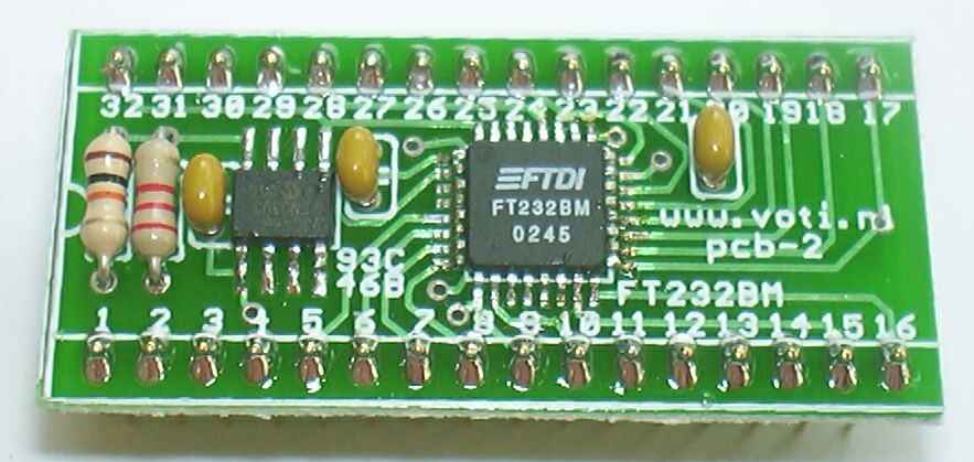
USB-2 : FT232BM / FT245BM TQFP to DIP adapter kit

Purpose
Circuit
Assembly
Use


Purpose

The USB-2 is PCB for experimenting with the FT232BM or FT245BM chips. The PCB accepts the FT232BM / FT245BM chip itself, and (optionally) the EEPROM, two resistors and three decoupling capacitors. The PCB has two rows of 16 pins in wide DIP format for inserting into a solderless breadboard or a DIP socket.

The FT232BM and FT245BM are TQFP SMD ICs with 32 very small legs, so this is definitely not a beginners kit.


Circuit

The circuit (click on the picture for a large pricture) shows that all 32 pins of the FT232BM / FT245BM chip are connected to the 2 x 16 pin rows. The optional 93C46B EEPROM and two resistors are connected as specified by the manufacturer. Three 0.1uF decoupling capacitors are also optional.


Assembly

I assume you know how to solder a PCB, otherwise this is definitely not a kit for you.

You will need a good soldering iron, a steady hand and most important: a good magnifying glass to check your work. A piece of thin solder and a piece of desoldering braid are supplied with the kit.

The most difficult component to solder is the FT232BM / FT245BM chip itself. There are basically two approaches to soldering an SMD chip like this: get it right the first time, or removing excess solder with desoldering braid. With my much-too-broad tip I can manage to get most of the pins right, using the braid for the one or two pins at each side that got too much solder. With a finer tip you might succeed to get all pins right.

When the tip of your iron is (too) big (like mine) the best tip I can give you is to use remove excess solder from the tip before using it, and to use as little solder as possible. This reduces the chance of making bridges. The kit contains some very thin solder, use it. It might seem to be a very short piece for the job, but you should not need more than half of it. Idem for the desoldering braid.

You can click on most of the pictures to get a larger picture.

The description assumes that you have the board oriented as shown, the numbers are readable and number one is in the bottom left corner.
The first component to solder is the FT232BM or FT245BM chip itself. It must be oriented as shown on the picture, text readable, dot at the upper left corner. Note that the PCB silcscreen might mention only 'FT232BM', because the same PCB is used for both chips. Place the chip exactly on its pads. You might want to use a drop of glue or some cellotape to hold it in place. Or put a littel solder on the first pad, and then put the leg on the hot solder. Solder one pin first, re-check the alignment of all pins, correct if necesarry. Solder the opposite pin, and check again. Once you solder more pins your chance of correcting a bad alignment is almost zero. Proceed with the other pins. Check your solder work with a magnifying glass, use the desolder braid to remove shorts. Be sure that the stuff you see between a leg and the pad is realy solder. Proceed to the next component only when you are realy sure that all connections are OK and without shorts. With the other components in place you will not be able to reach the chip to make corrections.
The next component is the EEPROM. It is SMD like the FT232BM, but its legs are much bigger so after doing the FT232BM this one will be easy. Place the chip with the text unreadable, dot (pin one) at the upper right corner.

Note that this component and the next two resistors are optional. If you want full freedom in experimenting you might not want to include these components.

Place and solder the 10 kΩ (brown-black-orange) and 2.2 kΩ (red-red-red) resitsors. These components are optinal.
Place and solder the three 100 nF capacitors. The marking on these capacitors is 104, which must be interpreted as 10 * 10^4 pF = 100 nF. These components are optional, but placing these capacitors on the PCB will provide better decoupling than placing them elsewhere.
Place and solder the two 16-pin strips. These strips are inserted from the bottom and soldered on the top (component side). The side with the shorter pins should be inserted into the PCB. Solder one pin of each strip first, assure that the strips are aligned correctly, then solder the other pins.


Use

The For the use of the FT232BM / FT245 BM chips refer to the information on the website of the manufacturer. Note that when the software tools are used to write to the EEPROM the VCP drivers must be used, and the virtual port drivers must not be installed (or de-installed) to use the VCP drivers.

The picture below shows the PCB with an FT232BM used in a breadboard circuit to interface to a PICmicro controller.

links
  FT232BM
  this PCB can also be used for the FT245BM


http://www.voti.nl/usb-2
Copyright (c) 2005 Van Ooijen Technische Informatica / Wouter van Ooijen