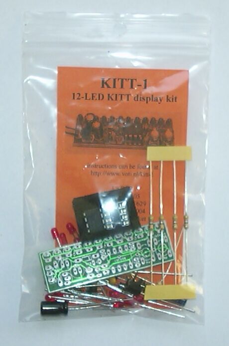
KITT-1
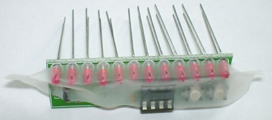
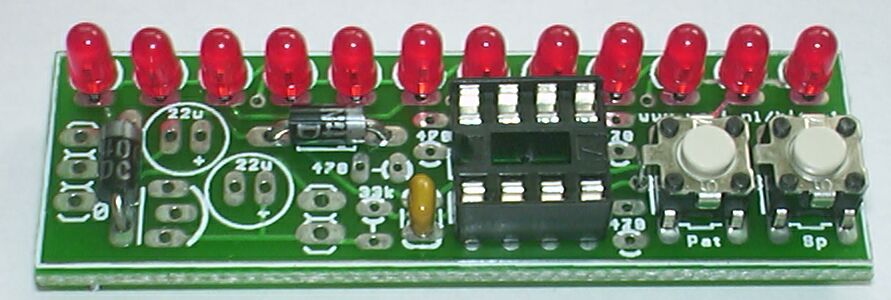
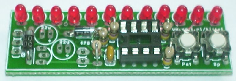
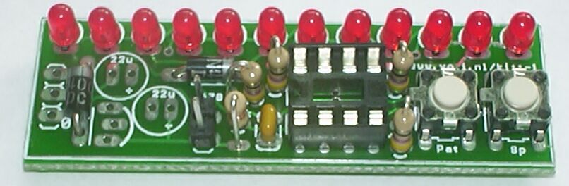
12-LED Kitt display kit
|
|
KITT-1
|
|
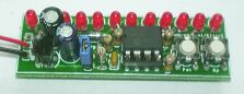
This is a kit for a 12-LED Kitt-display with a range of other patterns. The pattern and the speed can be selected using the two pushbutton switches.
The display can run on 9 .. 24 Volt AC or DC using the build-in regulator, or directly from 4.0 .. 5.5 Volt, which can for instance be provided by three 1.5 Volt batteries (not included).
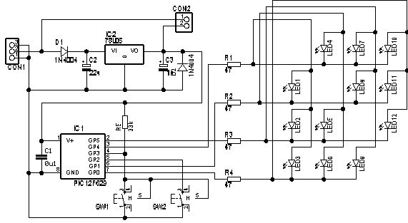
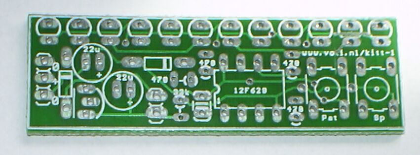
The circuit is deceptively simple because the PIC12F629 microcontroller does all the work. The PIC has an internal 4 MHz oscillator, so no external crystal, resonator or other oscillator components are needed. Switches SW1 and SW2 select the pattern and the speed for the display. SW1 has a pull-up resistor but SW2 does not need one because the PIC has internal configurable pull-ups for its pins (except unfortunately on GP3).
Only 4 pins of the PIC are used to drive 12 LEDs, using a matrix and taking advantage of all 3 possible states of a pin (low, high, input). The trick is that the PIC makes one of the pins high, while at the same time the pins corresponding to the LEDs that must be on are made low, and the pins that correspond to LEDs that must be off are made inputs (high impedance). Because the resistors are shared between the LEDs the PIC must vary the timing carefully to make the LEDs illuminate evenly.
The diode D1, elco C2 and the 78L05 regulator create 5 Volt from what is input on CON1. When jumper CON2 is placed the regulator is bypassed. In this case D2 provides some protection agains a reversed power.
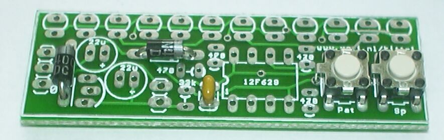
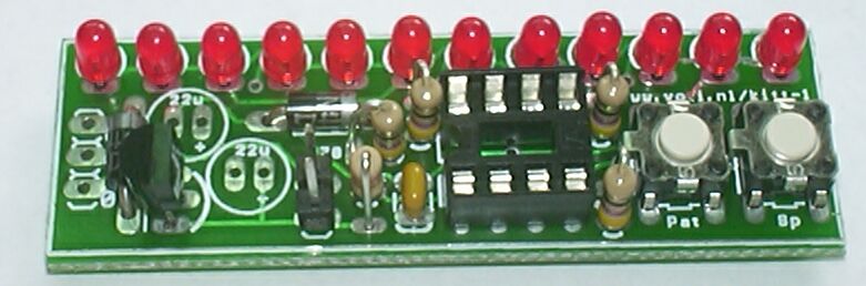
This kit is small but the components are closely packed on the PCB, so it requires carefull assembly, using the step-by-step instructions below. Take care to put the components in the correct orientation, as shown on the pictures. You can click on most pictures to get a larger one.
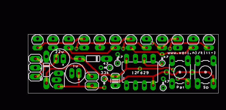
| The description assumes that you have the board oriented as shown, the with the row of LEDs at the top. |
|
|
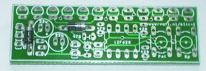
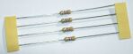
| Place and solder the two 1N4004 diodes. Watch the orientation: the white band on the diode must match the band on the silkscreen. |
|
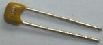
| Place and solder the 100nF capacitor. It is marked as "104". |
|
| Place and solder the two switches. You will need some pressure to push the switches in. |
|

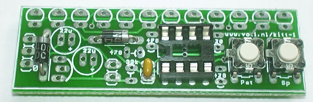
| Place and solder the IC socket. The notch must be at the left side. |
|
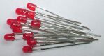
| Place the 12 LEDs. Take care: the longer wires must be at the top (at the border of the PCB). If you have cut the wires: the cup-like thingy inside the LED must be at the bottom (towards the other components). My way to solder the LEDs is first to use cellotape to hold them inplace. Next solder the longer wire of each LED, and cut the execess of this wire. Now look very carefull at the row of LEDs, and re-solder or bend them untill they are perfectly aligned. Any misalignment will show very clear when the display is used, and this is your chance to correct it. When the LEDs are aligned solder (and cut) the other wires. |
|
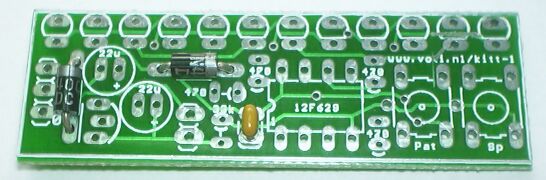
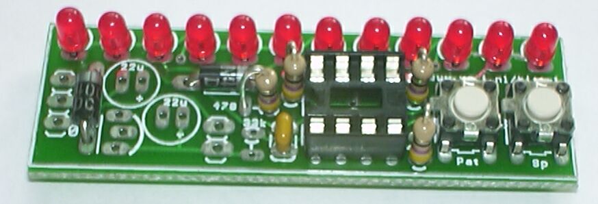
| Place and solder the four 47 Ω (yellow-purple-black) resistors. On older PCBs the silkscreen shows 470 (instead of 47) for thse resistors. |
|
|
| Place and solder the 33 kΩ (orange-orange-orange) resistor. |
|
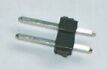
| Place and solder the two-pin header. |
|
|
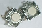
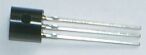
Place and solder the 78L05 IC.
NOTE: On older PCBs the silkscreen indicates that the round side should be oriented towards the centre of the PCB, but this is not correct, the round side must be towards the edge, as shown on the picture. |
|
|
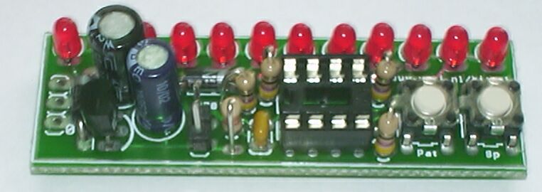
| Place and solder the two electrolytic capacitors. The larger one (22 uF) more towards the left/upper side, smaller one (1 uF) to the bottom/right of the bigger one. Note: both capacitors have a white band, which must be at the left side. |
|
|
If you want to use the display with a DC 4.0 .. 5.5 Volt supply place the jumper on
the two pin-header. For a higher-voltage supply do not place this jumper.
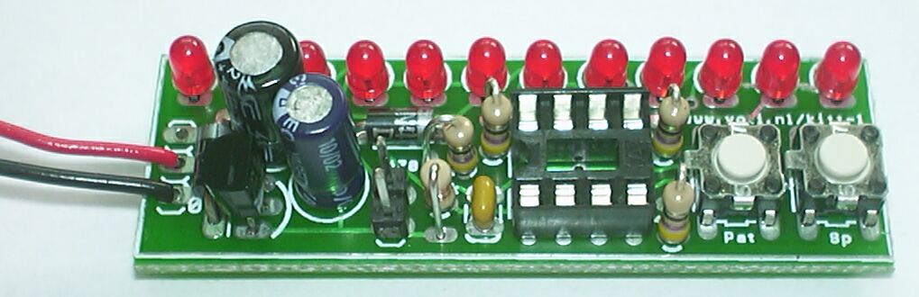
Solder two power wires to the power connections on the left of the PCB. The middle connection is the positive connection, the two outer ones are the negative connections. Connect the power. Check the voltage between the two leftmost pins of the socket: the bottom left pin must be +5 Volt relative to the top left pin. If this is not the cases you have done something wrong. You will have to find out what it is and correct it before placing the microcontroller. |
| |

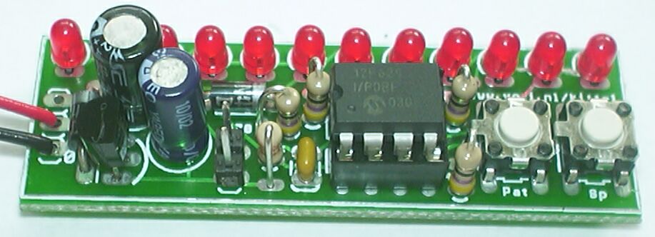
| Remove the power. Put the PIC microcontroller in its place in the socket. The dot must be at the lower left side. Reconnect the power. You should see some pattern on the LEDs. If not you have done something wrong, disconnect the power, find out what it is and correct it before reconnecting the power. |
|
As stated above the display can be powered either
|
from an unregulated 9 .. 24 Volt DC or AC source: Do not place the jumper J1. Apply the DC or AC source to the solder pads of CON1. Use the inner pad and one of the outer pads. For a DC source the inner pad must connect to the + (positive) lead. When the power is applied in reverse the diode D1 will protect the circuit. |
|
from a stable 4.0 .. 5.5 DC source: Do place the jumper J1. Apply the DC source to the solder pads of CON1, negative (-) lead to one of the outer pads, positive (+) lead to the inner pad. When the power is applied in reverse the diode D2 will short the power. When the display is used in a PC it is advised to use the 12 Volt from the PC PSU (with the regulator, do not place the jumper). When the 5 Volt would be used and it would accidently be reversed diode D1 could explode because the PSU can deliver far more current than the diode can handle. |
The display can show a variety of patterns, selected by pressing SW1 (the left switch). While SW1 is pressed down the display will show one of the patterns from the table below, to indicate the selected pattern.
| XXX--------X | Kitt : the calssic left-to-right and back Kitt display | |
| XXX-------X- | Kitt2: Kitt but with two LEDs on | |
| XXX-------XX | Snake: Kitt-like but with up to 12 LEDs on | |
| XXX------X-- | Kitt2: two 6-LED Kitt displays, mirrored at the centre | |
| XXX------X-X | Random: all LEDs light up at random | |
| XXX------XX- | Tardis: a random pattern is generated at the middle and shifted out, mirrored to both halves of the display (This somewhat resembles the trailer of the Dr Who television series.) | |
| XXX------XXX | Blink: all LEDs blink on and off | |
| XXX-----X--- | Beat: the LEDs mimic a the volume display for a 4-beat measure | |
| XXX-----X--X | Rotate: the LEDs light one by one, from right to left. If you put the LEDs in a circle this will generate a 'rotating' effect. | |
| XXX-----X-X- | Rotate2: As the previous, but with two LEDs on at any time. | |
| XXX-----X-XX | Up: Successively the LEDs are turned, when all are all on they are all switched off and it starts again. | |
| XXX-----XX-- | Up-Down: Successively the LEDs are turned, when all are all on they are switched off one by one, when all are off it starts again. |
The speed of the display can be selected by pressing SW2 (the right switch). While SW2 is pressed down the display will show the pattern XXXX----SSSS, where SSSS is the speed in binary form (XXXX for the highest speed, ---- for lowest speed). The speed will be increased by on each time SW2 is pressed, after the highest speed it will set to the slowest speed.
The selected pattern and speed are both stored in non-volatile memory, so when the power is removed and lateron restored the display will start with the last selected pattern and speed.
http://www.voti.nl/kitt-1
Copyright (c) 2003 Van Ooijen Technische Informatica / Wouter van Ooijen